 VoltDRAM
VoltDRAM
VoltDRAM
Why Is the Memory Module Manufacturing Process Important?
Every computer, server, and industrial controller depends on memory modules to move data quickly and reliably. The Memory module manufacturing process determines whether that reliability survives real working conditions. It covers component selection, printed circuit board assembly, chip placement, firmware programming, testing, and final inspection.
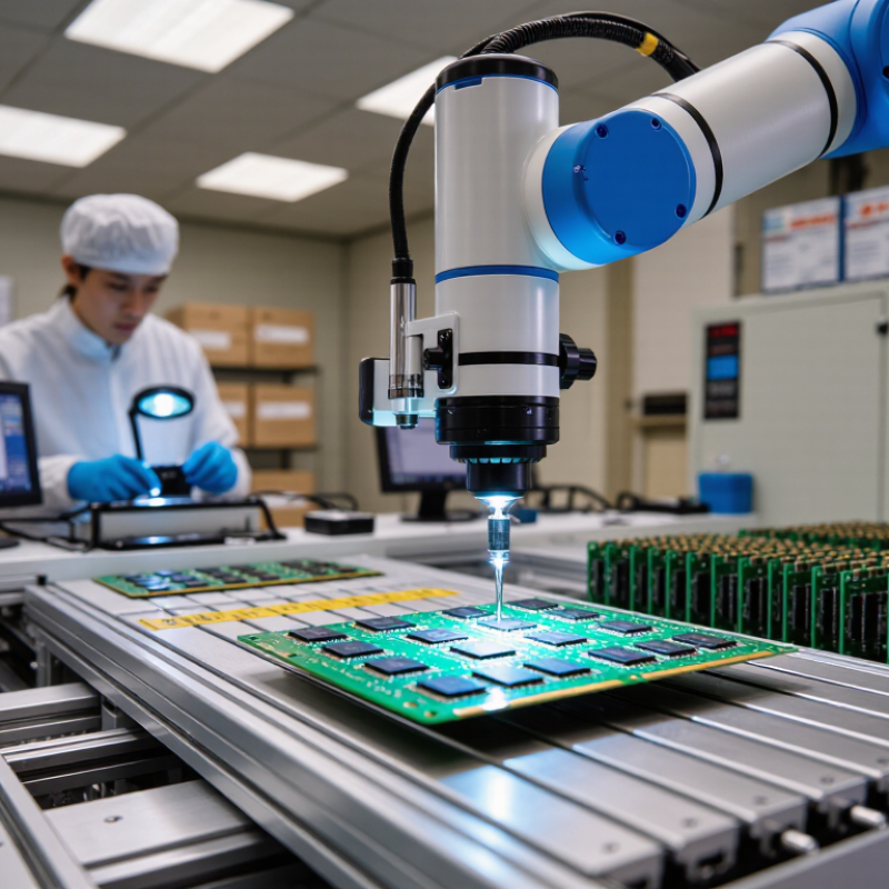
Small details matter. A technician checks solder joints under magnification. Automated systems measure signal quality at high speed. Thermal testing exposes weak modules before they reach a data center. Even packaging can influence moisture protection and long-term stability. These steps reduce errors, downtime, and expensive equipment replacement.
“Memory is the foundation of every digital system,” says semiconductor analyst Jim Handy. His statement captures the practical importance of manufacturing discipline. A module may look simple, but its performance depends on electrical timing, heat control, material quality, and consistent production records.
Manufacturers also need traceability. A clear lot number can connect one failed module to its components, machines, and inspection results. That evidence supports faster recalls and more honest quality decisions. It also strengthens customer confidence.
The process is not perfect. Human judgment can miss unusual defects, while automated testing may overlook failures that appear months later. This is where experience remains valuable. Engineers compare test data with field reports, then adjust designs or production controls.
A strong Memory module manufacturing process is therefore more than assembly. It is a layered quality system. It protects performance from the factory floor to the server rack. When manufacturers treat every solder point, test result, and handling step seriously, memory becomes a dependable part of modern computing.
A memory module is a removable circuit board that stores and moves digital data. It is commonly used in computers, servers, and embedded systems. The board connects to a memory slot through precisely shaped gold-plated contacts. Inside, several memory chips hold data as electrical charges. These chips are usually dynamic random-access memory devices, although other module types use different storage technologies.
The module also contains more than memory chips. A printed circuit board provides the electrical paths between every component. Small resistors and capacitors help control signals and stabilize power. Many modules include a small SPD memory chip, which stores information about capacity, speed, timing, and operating voltage. Some server-oriented designs add error-correcting features. A metal heat spreader may cover the chips, but it is not essential to every module.
Small details matter.
During inspection, engineers check solder joints, contact alignment, chip placement, and electrical performance. A module can look perfect and still fail under heat or repeated data transfers. Manufacturing therefore requires controlled assembly, clean handling, and repeated testing. The process is not only about attaching chips to a board. It is about keeping timing, voltage, and signal quality within narrow limits. One weakness can reduce system stability. I used to think capacity was the main measure, but that view is incomplete. Compatibility, durability, and tested performance often matter just as much.
| Manufacturing Dimension | What It Involves | Typical Module Content or Process Detail | Why It Matters |
|---|---|---|---|
| Memory Module Definition | A memory module is a printed circuit board assembly that provides system memory for electronic equipment. | It normally combines several memory devices, a circuit board, electrical contacts, and supporting components. | Creates a removable, standardized memory assembly that can be tested and installed as a unit. |
| Memory Devices | Memory devices store binary data as electrical charge or changes in resistance, depending on the memory technology. | Dynamic random-access memory devices are commonly used for working memory; non-volatile memory devices retain data without continuous power. | The memory devices determine the module's capacity, speed, power behavior, and data-retention characteristics. |
| Printed Circuit Board | The board provides mechanical support and electrically connects the memory devices and other components. | It contains copper traces, insulating layers, solder pads, plated holes, and an edge connector. | Accurate board design helps maintain signal integrity, structural strength, and reliable electrical connections. |
| Edge Connector | The edge connector is the exposed contact area used to connect the module to a compatible socket. | Contacts are arranged according to the module interface and are commonly protected with a metal surface finish to resist wear and oxidation. | Consistent contact dimensions and surface quality are essential for dependable installation and data transfer. |
| Module Layout | Engineers arrange memory devices and routing paths to meet electrical, thermal, and mechanical requirements. | Layout decisions include device placement, trace length matching, power distribution, grounding, and clearance around components. | A balanced layout reduces timing errors, electrical noise, overheating, and compatibility problems. |
| Surface-Mount Assembly | Automated equipment places components onto solder-coated pads on the circuit board. | The assembly sequence generally includes solder-paste printing, component placement, and controlled heating in a reflow oven. | Automation improves placement accuracy, repeatability, production efficiency, and solder-joint consistency. |
| Solder-Joint Quality | Solder joints create both the mechanical attachment and the electrical path between components and the board. | Inspection focuses on solder coverage, alignment, bridging, voids, insufficient solder, and open connections. | Defective joints can cause intermittent failures, data errors, or complete module malfunction. |
| Configuration Components | Some modules include components that identify supported operating parameters to the host system. | A serial presence detect memory device can store information such as capacity, supported timings, voltage requirements, and module organization. | Correct configuration information helps the system initialize and operate the module within safe specifications. |
| Error-Correction Support | Selected memory modules provide additional data bits or circuitry for detecting and correcting certain errors. | Error-correcting configurations commonly use extra memory devices or a wider data path than standard configurations. | Error correction improves data reliability in systems where undetected memory errors could affect operation or calculations. |
| Thermal Management | Manufacturing must account for heat generated by memory devices and power-related components. | Design measures may include adequate spacing, copper areas, airflow clearance, thermal interfaces, and heat spreaders where required. | Controlling temperature supports stable performance and helps reduce heat-related degradation. |
| Electrical Testing | Completed modules are tested for continuity, operating voltage, signal behavior, capacity, and functional performance. | Testing may include automated electrical tests, memory read/write patterns, speed verification, and operation across specified conditions. | Testing identifies assembly defects and performance failures before the module reaches the end user. |
| Visual and Automated Inspection | Inspection checks the module for manufacturing defects that may not be visible during electrical testing alone. | Inspection can verify component presence, polarity, placement accuracy, solder quality, connector condition, and board cleanliness. | Early defect detection improves yield, traceability, and long-term product reliability. |
| Reliability Screening | Reliability evaluations expose modules to controlled electrical, thermal, and mechanical stresses. | Common evaluations include temperature cycling, operating-life testing, humidity exposure, vibration, and connector insertion testing. | Screening helps reveal weaknesses that may otherwise appear only after extended field use. |
| Process Control | Manufacturers monitor material quality, equipment settings, soldering conditions, and inspection results throughout production. | Important controls include moisture management for boards and components, reflow-temperature profiles, placement accuracy, and defect records. | Consistent process control reduces variation between production batches and supports predictable performance. |
| Final Packaging and Handling | Finished modules must be protected from electrostatic discharge, moisture, contamination, and physical damage. | Typical measures include antistatic packaging, moisture-resistant materials when needed, protective separators, labeling, and controlled handling. | Proper packaging preserves the module's electrical and mechanical condition during storage and transportation. |
Reliable modules balance density, voltage, timing, and board layout. They must behave predictably across workloads and temperatures. Speed alone is insufficient.
Short, balanced traces reduce reflections and timing errors. Correct configuration data helps the system select safe operating settings. Small layout mistakes can cause intermittent failures.
Error-correcting memory can detect and correct selected bit errors during normal operation. It cannot fix every failure. Still, it adds useful protection.
A precision stencil applies solder paste to the circuit board. Placement machines position chips and small components. The board then passes through a controlled reflow oven.
Optical inspection checks alignment, orientation, and visible damage. X-ray inspection can examine hidden joints. Machines help, but operators still need to review suspicious results.
Repeated heating and cooling can expose weak solder joints and material expansion problems. A module may pass a short benchmark and fail later. That result needs investigation.
Small variations in impedance, voltage, or timing can cause boot failures and crashes. Physical fit does not guarantee system compatibility. Firmware and configuration settings also matter.
Check the required memory standard, voltage, capacity, rank layout, and configuration profile. Confirm compatibility with the processor and motherboard. Do not trust appearance alone.
Traceability connects each module with materials, equipment settings, inspections, and failures. Records support faster analysis when problems appear. Without them, explanations become guesses.
A memory module is a compact electronic assembly that combines memory chips, a printed circuit board, power-management elements, and supporting components to store and transfer data efficiently. Its design must balance speed, capacity, power consumption, thermal behavior, and signal integrity. Careful engineering helps the module perform reliably across different operating conditions while maintaining compatibility with appropriate systems.
The memory module manufacturing process involves circuit-board preparation, component placement, soldering, firmware or configuration programming, and detailed inspection. Automated production equipment and precise assembly controls help prevent connection defects and improve consistency. Quality testing may include electrical verification, data-transfer tests, thermal evaluation, and extended stress testing to identify unstable units before shipment. Manufacturing precision also affects overall cost because accurate processes reduce material waste, rework, and failure rates. At the same time, consistent dimensions, electrical specifications, and configuration standards are essential for compatibility, making precision a key factor in dependable and cost-effective memory production.
